Gantner Instruments has developed an Ethernet communication interface that transfers data from the Moog Aerospace Test Controller to the Q.series measurement system. Controller signals such as command, feedback, control error and flight spectrum information are continuously sent to the Q.series data acquisition measurement system for online storage, monitoring and analysis. This reduces the burden of post-test data analysis.
Q.series Measurement System
The innovative Q.series system has been designed to meet the most demanding testing environments. The Q.series features high speed, high accuracy and reliability. The system is modular, highly scalable, and comes with a wide range of measurement modules. This is advantageous for test system architecture options and test lab environments. Each measurement module has been optimized to provide the best price to performance ratio available on the market.
The Ethernet communication interface with the Moog Aerospace Test Controller is handled by a plugin that runs on the Q.series’ programmable real-time controller, the Q.station. The Q.station firmware features a plugin management system that supports easy deployment and maintenance of custom communication protocols.
For installation and connection details, please refer to the Q.series product manual. All manuals are available for download.
Moog Aerospace Test Controller
The Moog Aerospace Test Controller is a digital servo controller designed for static and fatigue testing of aircraft structural components. Its unique architecture and control loop design allows for synchronized closed-loop control of up to 500 servo actuators. Test setup, operation, and monitoring is done through the Aerospace Test Suite software.
Ethernet communication interface
The communication interface between the Aerospace Test Controller and the Q.series system is done via a bi-directional Ethernet communication protocol, which allows for easy configuration and operation. The protocol consists of three different interfaces:
- Controller data that is sent from the Moog Aerospace Test Controller to the Q.series system
- “Handshaking” interface to send commands and statuses from and to the Test Controller
- Measurement data that is sent from the Q.series system to the Moog Test Controller
For each control channel the following signals are send to the Q.series system:
- Force command
- Force A feedback (load cell bridge A)
- Force B feedback (load cell bridge B)
- Position feedback
- Servo valve current
- Force control error
- Position control error
In addition, for each Aerospace Test Controller a set of Shared Memory channels (virtual calculation channels) are sent to the Q.series system. The number of Shared Memory channels depends on the controller configuration; minimum 64 channels, maximum 1280 channels.

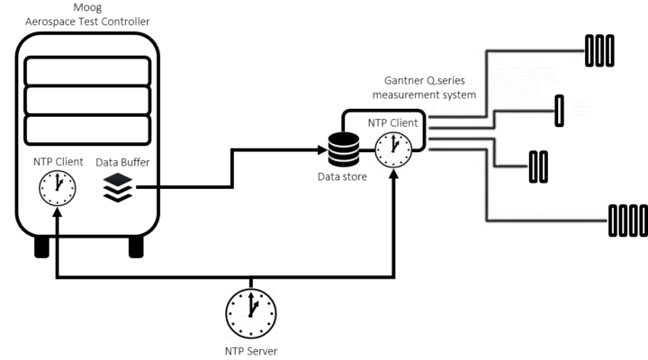
The Aerospace Test Controller buffers the data, which is then polled by the Q.series system at fixed intervals. The Aerospace Test Controller buffers its data at either 100 Hz, 200 Hz, or 500 Hz. Both systems are time synchronized using a networking protocol for clock synchronization. Typically, the NTP server is installed on one of the workstations. Both the Aerospace Test Controller and the Q.series system slave to the NTP server. For more information about configuring the Q.series’ NTP client, please refer to Chapter 6 of the Q.station manual.
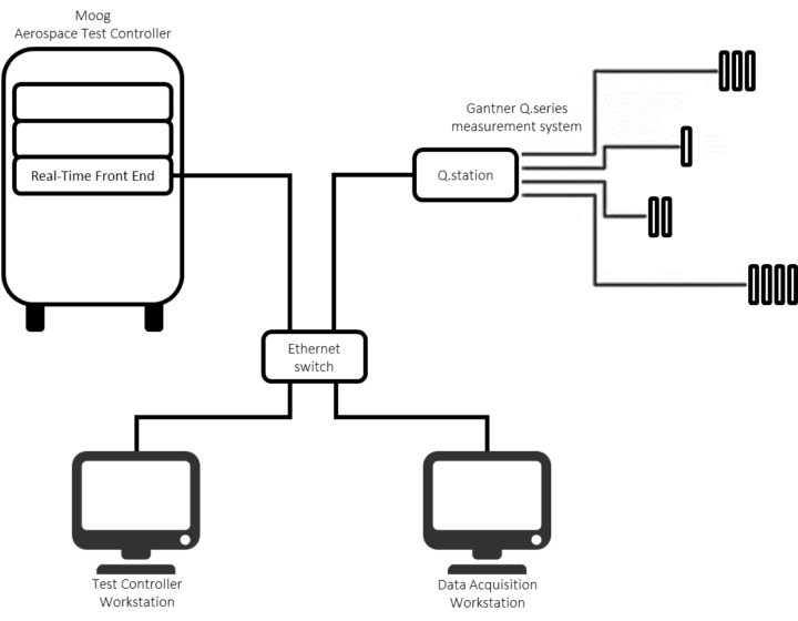
The Q.series system, Moog Aerospace Test Controller, and workstation(s) should all be in the same network range. To connect the Aerospace Test Controller to the Q.series system standard Ethernet cables and a 1 Gb/s Ethernet switch are used. Connect the Office Network port on the Aerospace Test Controller to the switch. On the Q.station the Ethernet TCP/IP port should be used. A Moog Plugin Configuration Tool is provided with the Q.series system to configure the settings of the plugin, i.e. IP addresses, channel selection and time sync alarm. Usually it is not required that all Test Controller channels are recorded. To minimize data overhead, a search filter can be added to quickly select a subset of Test Controller channels for recording.

Fully configurable data loggers

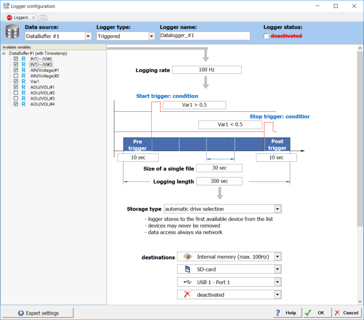
The Q.series allows for up to 20 unique data loggers. Each data logger can be configured for continuous, triggered or event-based data recording. Each logger can be setup to record a different data set with a different logging rates. For example, one logger can be configured for continuous data recording to a network location. In parallel, a high-speed data logger can be set up with a pre- and post-trigger time in case an unexpected event occurs. File name, size, destination, and protection level are fully configurable for each data logger. Each logger can write data to a different location, either the internal flash memory, an SD-Card, SATA hard drive, USB flash drive or any connected network drive. For more information about recording data using the data logger, please refer to the Q.station manual.
User Benefits
- Reduce sensor wiring and cost: all controller data is transferred over a single Ethernet cable. There is no need for extra wiring of sensors, such as load cells, to both the control and measurement system.
- Distributed system architecture: the Q.series system can be distributed around the test article, resulting in significantly shorter transducer cables between measurement modules and thousands of strain gauges.
- Connect multiple Moog tests to one Q.station: the Moog Aerospace Test Controller can run up to 5 tests in parallel. Each test has its own data port. All data ports can be connected to one Q.station, saving cost on additional measurement hardware.
- On-line monitoring and analysis of test data: ability to monitor and analyze the control and measurement data at all times and to immediately inform the user and/or stress analyst when deviations occur.
- Assured data availability: the Q.series system has 3 levels of redundancy for assured data availability. Measurement data can be broadcast in parallel to an online database as well as to an FTP backup server. Both data ports are continuously monitored. If a broadcast fails, the Q.series system will automatically start logging data to its local disk.
- Build-in time sync monitoring: the Q.series provides a unique functionality that allows monitoring of the clock time difference between the Moog Aerospace Test Controller and the Q.series system. In the event that the clock time difference is outside a pre-defined threshold an alarm is generated to inform the operator. This avoids unacceptable data skew or jitter.
For more information please contact s.ploegmann@gantnerinstruments.com
More articles
Introducing GI.bench – Enhanced DAQ Capabilities for Engineering Excellence
Take Your Data Acquisition to the Next Level
Engineers and technicians frequently encounter significant challenges in managing complex data acquisition setups, including massive data volumes, the integration of diverse devices, and the requirement for real-time insights. Addressing these challenges head-on, Gantner Instruments proudly announces the latest evolution of our industry-leading software, GI.bench.
Innovation Call Vorarlberg 2023
Digital Innovation: Fueling the Future and Unveiling the Unseen
Read more...Enhanced Functionality with GI.bench’s Newest Release: Revamped UI, Powerful Tools and More!
Introducing the latest update to our powerful and intuitive testing and measurement software - GI.bench. This update promises to elevate your testing capabilities with features designed to streamline your workflow and maximize productivity.
Read more...Instrumentation, Analysis, and Testing Exhibition 2024
Gantner Instruments at the Instrumentation, Analysis & Testing Exhibition 2024!
Read more...