1. Know your application
If you face the challenge of setting up a vibration measurement system for a rotating machine, you need to know the mechanical design and bearing of the shaft. There is a significant difference between measuring vibration of ball bearings and plain bearings. Ball bearings use accelerometers, while plain bearings use proximity probes or both.
2. Environmental and surface temperature
Keep in mind that not all types of accelerometers can be used in very high or very low surface or ambient temperatures. There are accelerometers with built-in electronic components in their sensor casings and sensors without electronic components. Sensors with integrated electronics, such as MEMS and IEPE accelerometers can be used up to 120°C / 248°F (MEMS) and 150°C to 200°C (302°F to 392°F) (IEPE) surface or ambient temperature. For high temperature applications, such as measurements on gas turbines, pipes, and vessels, piezoelectric (PE) sensors must be used.
3. Vibration or shock?
Standard accelerometers are suitable for measuring random vibration on machines, structures, and other components. However, for shock measurements, e.g. in crash tests, very high accelerations occur, so that special accelerometers are required. For these types of tests, use PE accelerometers for a broad measurement range up to 50,000g or MEMS sensors based on piezoresistive sensing elements.
4. Measuring in high-frequency ranges down to DC
Depending on the application, the frequency response of the sensor is essential for measuring every frequency of interest. When measuring structures such as bridges or towers (e.g., wind turbines and modal analysis) the frequency of the vibration measured can be very low, sometimes below 0.5Hz or down to DC. For these applications, you should use sensors with a frequency response down to DC. MEMS-based accelerometers are suitable for the job.
5. Sensor mounting and frequency response
In applications such as machine monitoring, the vibration must be measured over a broad frequency range. Rotating machines with 3000 rotations per minute or higher and roller bearings have frequencies of interest exceeding 3-5kHz. To view the harmonics of these signals, the frequency response of the sensor(s) used must be higher than 3-5kHz. The sensor’s maximum frequency response depends on its fixation on the surface of the measured object. For signal frequencies higher than 3kHz, magnets can be used. However, for the best measurement results, especially for frequencies exceeding 10kHz, the sensors must be fixed with adhesives or mounting studs.
6. Routing and fixing the sensor cable
To measure the vibration of an object, you want to mount the sensor on it, but not have induced vibrations from other parts. Therefore, the sensor cable must also be laid with great care with fixation at several points. With free-flying cables, additional vibration can be introduced by components other than the object measured. This introduced vibration affects the sensor and distorts the signal you wish to measure. Especially when using Piezoelectric sensors, the movement of the cable from the sensor to the charge amplifier can cause charge changes to be transferred with this cable.
7. Avoiding noise in the measured signal
If you see noise in your measurement signal, especially at 50/60Hz, you most likely have a ground loop. Ground loops can transmit interference to the measurement signal as noise, most common at a line frequency of 50/60Hz. Ground loops develop when a common line (e.g., signal return/shield of an IEPE accelerometer installation) is grounded at two points of differing electric potential. To avoid such ground loops, connect the cable screen only at a place to ground potential and use electrical isolated sensing elements when possible.
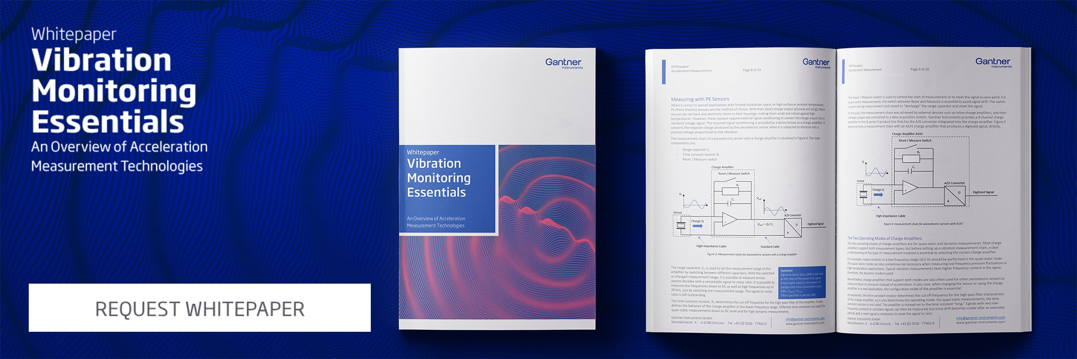
8. How does the time constant of a charge amplifier affect measurements?
There is a fundamental difference between the two operating modes of charge amplifiers for quasi-static and dynamic measurements. Most charge amplifiers support both measurement types. But before setting up a vibration measurement chain, a clear understanding of the desired measurement is essential to select the right charge amplifier operation mode. For example, measurements in exceptionally low-frequency ranges <0.5Hz should be performed with the quasi-static mode. This is sometimes the case when measuring low frequency pressure fluctuations in high-temperature applications. Typical vibration measurements have a higher frequency content in the signal; therefore the dynamic mode is used.
The time constant of the charge amplifier defines the operating mode for static or dynamic measurements.
9. What is the maximum cable length for an IEPE sensor?
IEPE sensors are powered by a constant current and a DC voltage. The AC signal of the measured acceleration is superimposed on the supply voltage. As a rule of thumb, the higher the constant current, the greater the cable length can be. But keep in mind: maximum cable length depends also on cable quality. Most signal conditioners and I/O-modules for IEPE sensors provide a 4mA constant current that forms a very good optimum between noise immunity, cable length, signal frequency, and current consumption. Measurements with cables longer than 80 m or even 100 m are possible.
10. Does the supply voltage for a MEMS-based accelerometer matter?
The short answer is yes, the supply voltage does matter. Most MEMS sensors have a built-in voltage regulator but are very sensitive to the quality of the supplied input voltage. The quality of the voltage source must be high, should be regulated within +/-0.1%, and the noise and ripple must not exceed 1.5mV RMS. I/O modules designed specifically for MEMS-based sensors provide a stable power supply, and when using these devices, the supply voltage does not cause headaches.
This is how to select the appropriate accelerometer
Download our free whitepaper Vibration Monitoring Essentials for more detailed technical information about acceleration measurement, including the pros and cons for each of the three absolute vibration transducers PE, IEPE, MEMS used for measuring acceleration.
More articles
Staying Ahead of the Curve: Meeting the Challenges of EV Powertrain Testing
In this blog post we show in advance the technical challenges of testing electric vehicles and measuring power quality and how the innovative solutions from Gantner Instruments can help to overcome these challenges.
Read more...Gantner on expansion course
In 2014 Gantner Instruments GmbH moved into its new, energy-efficient company building in Schruns. The modern building with an area of 1000 m² has been designed from the beginning to offer the possibility of extension. This option was used in 2017 by the company, which has a steady double-digit growth per year since its inception.
Read more...Gantner Instruments at Aero Engine Testing 2025
On March 20–21, 2025, aerospace professionals, industry experts, and technology providers will gather in Mianyang for the 2025 Aerospace Equipment Digital Intelligence Test and Industry Development Conference. Under the theme “Digital Leadership in Aviation, Intelligent in the Blue Sky,” this event highlights cutting-edge progress in advanced aircraft engine digital intelligent testing, high-precision measurement, combustion, turbine, and strength testing. One main forum and five sub-forums will feature experts sharing insights and best practices, while an aircraft engine test technological achievements and product exhibition showcases the latest innovations.
Read more...Gantner Instruments at Battery Conference 2025 in Aachen
Gantner Instruments will showcase high-precision measurement solutions for battery testing at Battery Conference 2025 in Aachen, including Battery Day NRW on April 1.
Read more...