DAQ Systems
Overview
Introduction to DAQ Systems
Data acquisition systems (DAQ or DAS) collect information from connected sensors and other instrumentation to measure and record electrical and physical quantities, such as voltage, current, temperature, strain, pressure, shock, vibration, distance, displacement, RPM, Angle, and weight. A DAQ System typically consists of sensors, measurement hardware with signal conditioning and an Analog-to-Digital converter, and a computer with programmable software for data logging and analysis.
Did you know?
Gantner Instruments DAQ systems are fully operational with data logging and analysis standalone without connected a PC.
Components of DAQ Systems
A complete DAQ system consists of the Software, Controller, DAQ module(s), and Sensor(s).
Data acquisition systems convert the signals from connected sensors from analog to digital values and send this data to the controller. Controllers process and store the collected data. The data streams can be filtered, merged, and stored (by an event). With the help of software (usually on a PC), the streamed data can be visualized, analyzed, or post-processed.
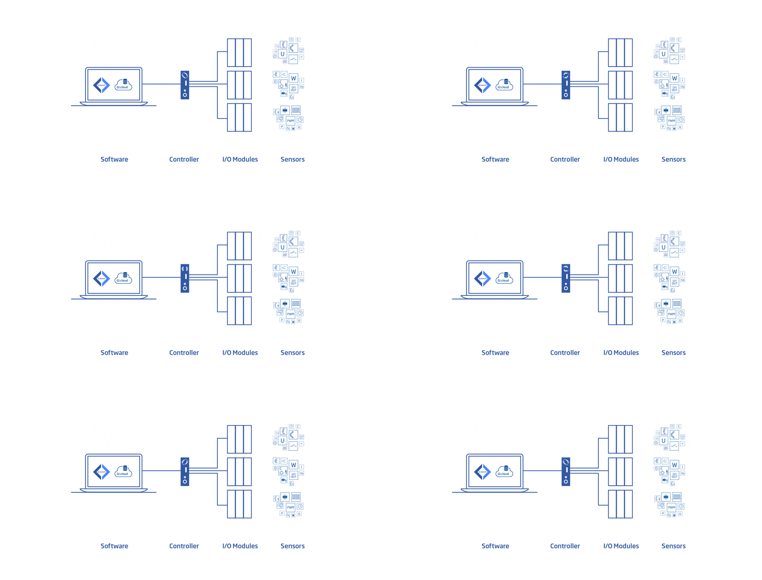
Software
GI.bench is a one-time purchase, subscription-free software suite for quick and easy setup of measurement channels, data loggers, and dashboards. Connect data with third-party applications, promote interoperability, and expand your analysis capabilities using our advanced open API.
Controller
Controllers process and store the collected data internally or externally, and can stream that data to various destinations such as Software on a connected PC or to a Cloud solution.
Modules
DAQ modules measure the signals of connected sensors and convert them from analog to digital values to be sent to the Controller for further processing.
Accessories
No DAQ system is complete without accessories like cables, terminals, etc., but which ones can vary greatly between test and measurement applications across various industries.
Sensors
Sensors produce an output signal to sense a physical event or phenomenon, detect events or changes in its environment, and send the information to the connected DAQ Modules.
Discover Gantner Instruments DAQ
Quality
Our ingenious circuitry guarantees accurate, precise, and stable measurement of temperature sensors, strain gauge signals, complex frequency signals, and voltages up to 1500 V.
Synchronization
Enjoy virtually jitter-free time-synchronous data across scalable multi-system, high-density, distributed solutions using, e.g., IRIG-B, GPS, NTP, PTPv2 protocols, and EtherCAT DC.
Flexibility
Tailor mixed-measurement systems exactly around your needs, from measurement types to form factors; our systems can adapt and stay relevant as your needs grow.
Reliability
Our measurement systems are exclusively based on proven industry standards so that you can take full advantage of our best-in-class MTBF of more than 20 years.
Scalability
Up to thousands of channels worth of modular I/O products can be connected in any sequence or group and distributed along test rigs with interconnecting cables on an as-needed basis.
Connectivity
Safe and reliable data exchange and interoperability through various read/write interfaces at the edge, desktop, and cloud level and modern APIs for device configuration and data stream access.
Safety
All Gantner products feature galvanic isolation up to 1500 VDC between every channel, bus, and power supply and include industry-standard high-safety connector options.
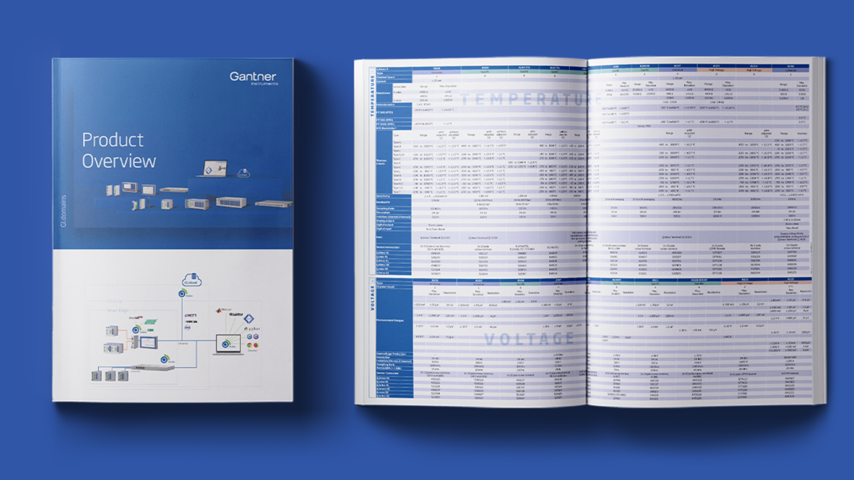
Our DAQ Systems
Gantner Instruments offers modular and flexibile DAQ system configurations. We are committed to deliver upwards compatibility across our entire range of products and systems to enable our customers to utilize their existing instrumentation and software for decades to come with lifetime calibration support.
Q.series X
The NeXt level in performance and technological advancement of the Q.series Classic, Gantner’s Q.series X data acquisition systems offer high-performance signal conditioning with flexible interfaces and form factors, higher ADC, and data rates. Q.series X is capable of distributed and daisy chained setups, as well as reconfiguration during operation, and offers a variety of connector options.
Q.series Classic
Flexible Form Factors
We offer a variety of modular packaging styles and the ability to swap between them.
Choose between Distributed and Flexible, Portable and Compact, or Multi-channel Measuring Systems. Front plates, connectors, and I/O cards are interchangeable between bloxx, brixx, and raxx (3U), so you can always adapt your system’s housing with minimal investment.
Pick a Controller
We offer a variety of controllers varying in scalability, performance, interfaces, internal storage, PLC programmability, and physical size. Choose between the Q.station X, Q.monixx, and Q.core for our Q.series X DAQ systems (Ethernet, CAN, Profibus, and EtherCAT), and we offer the Q.station 101 for our Q.series Classic DAQ systems (Ethernet, CAN, and Profibus).
Ethernet, CAN, ProfiNet
Connect up to 64 DAQ modules per controller for reliable 24/7 PC-less operation. Create independent, multifrequency data loggers, and utilize powerful arithmetic functions. Fieldbus interfaces, support for publish/subscribe and messaging protocols and customer-specific communication protocols.
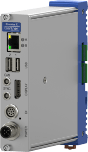
EtherCAT
Configure with EtherCAT masters like TwinCAT or KPA. Option to use the computational functionality of a Q.station controller or full EtherCAT functionality with an EC bus coupler.
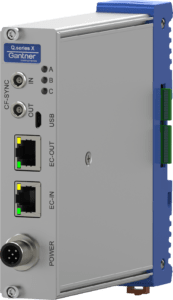
All-in-One Edge Device
The Q.monixx is a controller with built-in analog and digital I/O, ideal for remote monitoring & control, computer independent data logging, remote configuration, and universal connectivity.
High-performance data processing
The Q.core is a high-performance controller for connecting up to decentralized controllers, data clients, peripherals, and includes 1TB SDD packed in a 1U (1.75”) 19-inch rack-mount space.
Measurement and I/O modules for all Relevant Signals
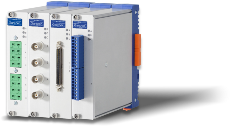
Q.series X I/O Signal inputs Design – ANALOG
I/Os for almost all sensor
Strain gage module with DC and CF excitation
-
Voltage
-
Current
-
Resistance
-
Potentiometer
-
RTD / Cryogenic thermistor
-
Thermocouple
-
Strain gage: Full-, Half-, Quarter-Bridge
-
Inductive full-& half bridge
-
LVDT
-
IEPE / Charge
-
Analog output
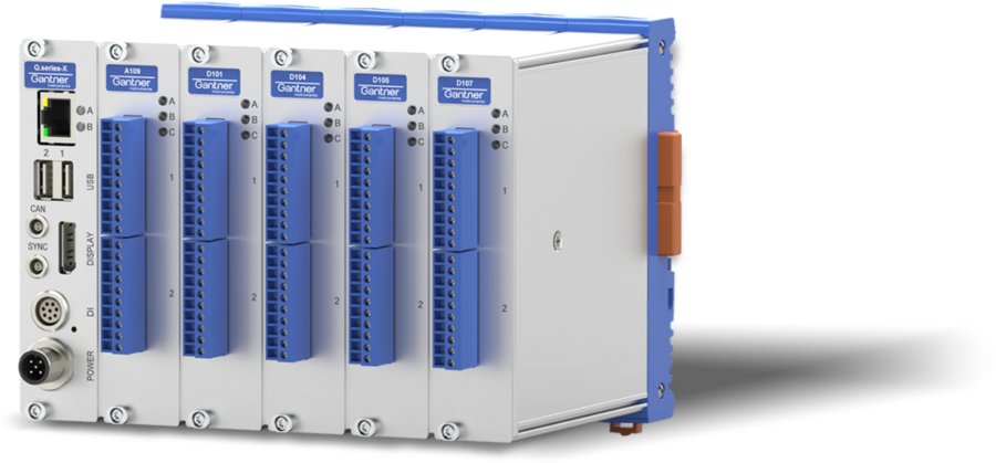
Q.series X I/O Signal inputs Design – DIGITAL
Frequency, PWM: Input and output
Specials: Quadrature, up/down counter, missing tooth detection, chronos method
-
Frequency / Counter
-
Pulse-width modulation
-
Time
-
Status
Q.series X I/O Signal inputs Design – HIGH VOLTAGE
Inputs for voltage, current, thermocouples, Pt100, NTC, IEPE, strain gage and much more

-
Voltage
-
Current
-
Resistance
-
RTD
-
Thermocouple
-
Strain gage
-
IEPE
Software that Connects You
Open and scalable software platforms with data processing and analytics.
Configure, operate and visualize your data
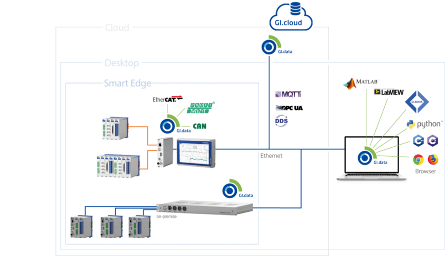
Our software platform allows teams to monitor dashboards on any computer or mobile device using a web browser without needing additional software. Connect data with third-party applications, promote interoperability, and expand your analysis capabilities using our advanced open API.
GI.bench - Data Acquisition Software
GI.bench is a state-of-the-art data acquisition software environment that combines system setup and configuration and logging and monitoring multiple data streams in one easy-to-use desktop application.
GI.cloud - Data Acquisition in the Cloud
The GI.cloud enables the acquisition and processing of data from distributed measurement devices. GI.cloud combines Gantner’s proven edge devices for monitoring and control with an adaptive and scalable cloud backend.
GI.connectivity - Open and Flexible
GI.connectivity provides safe and reliable data exchange and interoperability through various read/write interfaces at the edge, desktop, and cloud levels. GI.connectivity will transform your Q.series X system into the most open and flexible data acquisition and streaming platform available.

We are available to answer questions about applications and products or help you with complete test and measurement setups. As a special thank you for purchasing Gantner Instruments products and services, we are committed to providing you with free personalized support from our technical specialists over the lifetime of your investment – without any barriers.
FAQ
These are frequently asked questions regarding our DAQ Systems:
A data acquisition system is a combination of hardware and software used to collect, digitize, and process measurements from real-world phenomena. In simplified terms, a DAQ system takes analog signals from sensors (for example, voltage from a thermocouple, strain gauge, pressure transducer, etc.) and converts them into digital data that a computer can store and analyze. The hardware typically includes sensors/transducers, signal conditioning (amplifiers, filters), and analog-to-digital converters (ADCs), as well as a communication interface to a PC. The software component provides the user interface and data logging, visualization, and often control or feedback functions. In essence, a DAQ system allows you to measure physical parameters like temperature, force, acceleration, electrical signals, etc., and acquire those readings into a computer for monitoring or analysis. For example, a DAQ setup might read a temperature sensor’s voltage, convert it to a digital value with a timestamp, and feed it into logging software that shows temperature vs. time. “DAQ” and “data acquisition” are broad terms – they can range from a simple USB data logger with one input channel up to very sophisticated high-speed systems with hundreds of channels. The core idea, however, is acquiring accurate, timely data from the physical world for further use.
A data acquisition system is a combination of hardware and software used to collect, digitize, and process measurements from real-world phenomena. In simplified terms, a DAQ system takes analog signals from sensors (for example, voltage from a thermocouple, strain gauge, pressure transducer, etc.) and converts them into digital data that a computer can store and analyze. The hardware typically includes sensors/transducers, signal conditioning (amplifiers, filters), and analog-to-digital converters (ADCs), as well as a communication interface to a PC. The software component provides the user interface and data logging, visualization, and often control or feedback functions. In essence, a DAQ system allows you to measure physical parameters like temperature, force, acceleration, electrical signals, etc., and acquire those readings into a computer for monitoring or analysis. For example, a DAQ setup might read a temperature sensor’s voltage, convert it to a digital value with a timestamp, and feed it into logging software that shows temperature vs. time. “DAQ” and “data acquisition” are broad terms – they can range from a simple USB data logger with one input channel up to very sophisticated high-speed systems with hundreds of channels. The core idea, however, is acquiring accurate, timely data from the physical world for further use.
A data acquisition system is a combination of hardware and software used to collect, digitize, and process measurements from real-world phenomena. In simplified terms, a DAQ system takes analog signals from sensors (for example, voltage from a thermocouple, strain gauge, pressure transducer, etc.) and converts them into digital data that a computer can store and analyze. The hardware typically includes sensors/transducers, signal conditioning (amplifiers, filters), and analog-to-digital converters (ADCs), as well as a communication interface to a PC. The software component provides the user interface and data logging, visualization, and often control or feedback functions. In essence, a DAQ system allows you to measure physical parameters like temperature, force, acceleration, electrical signals, etc., and acquire those readings into a computer for monitoring or analysis. For example, a DAQ setup might read a temperature sensor’s voltage, convert it to a digital value with a timestamp, and feed it into logging software that shows temperature vs. time. “DAQ” and “data acquisition” are broad terms – they can range from a simple USB data logger with one input channel up to very sophisticated high-speed systems with hundreds of channels. The core idea, however, is acquiring accurate, timely data from the physical world for further use.
A data acquisition system is a combination of hardware and software used to collect, digitize, and process measurements from real-world phenomena. In simplified terms, a DAQ system takes analog signals from sensors (for example, voltage from a thermocouple, strain gauge, pressure transducer, etc.) and converts them into digital data that a computer can store and analyze. The hardware typically includes sensors/transducers, signal conditioning (amplifiers, filters), and analog-to-digital converters (ADCs), as well as a communication interface to a PC. The software component provides the user interface and data logging, visualization, and often control or feedback functions. In essence, a DAQ system allows you to measure physical parameters like temperature, force, acceleration, electrical signals, etc., and acquire those readings into a computer for monitoring or analysis. For example, a DAQ setup might read a temperature sensor’s voltage, convert it to a digital value with a timestamp, and feed it into logging software that shows temperature vs. time. “DAQ” and “data acquisition” are broad terms – they can range from a simple USB data logger with one input channel up to very sophisticated high-speed systems with hundreds of channels. The core idea, however, is acquiring accurate, timely data from the physical world for further use.
A data acquisition system is a combination of hardware and software used to collect, digitize, and process measurements from real-world phenomena. In simplified terms, a DAQ system takes analog signals from sensors (for example, voltage from a thermocouple, strain gauge, pressure transducer, etc.) and converts them into digital data that a computer can store and analyze. The hardware typically includes sensors/transducers, signal conditioning (amplifiers, filters), and analog-to-digital converters (ADCs), as well as a communication interface to a PC. The software component provides the user interface and data logging, visualization, and often control or feedback functions. In essence, a DAQ system allows you to measure physical parameters like temperature, force, acceleration, electrical signals, etc., and acquire those readings into a computer for monitoring or analysis. For example, a DAQ setup might read a temperature sensor’s voltage, convert it to a digital value with a timestamp, and feed it into logging software that shows temperature vs. time. “DAQ” and “data acquisition” are broad terms – they can range from a simple USB data logger with one input channel up to very sophisticated high-speed systems with hundreds of channels. The core idea, however, is acquiring accurate, timely data from the physical world for further use.
A data acquisition system is a combination of hardware and software used to collect, digitize, and process measurements from real-world phenomena. In simplified terms, a DAQ system takes analog signals from sensors (for example, voltage from a thermocouple, strain gauge, pressure transducer, etc.) and converts them into digital data that a computer can store and analyze. The hardware typically includes sensors/transducers, signal conditioning (amplifiers, filters), and analog-to-digital converters (ADCs), as well as a communication interface to a PC. The software component provides the user interface and data logging, visualization, and often control or feedback functions. In essence, a DAQ system allows you to measure physical parameters like temperature, force, acceleration, electrical signals, etc., and acquire those readings into a computer for monitoring or analysis. For example, a DAQ setup might read a temperature sensor’s voltage, convert it to a digital value with a timestamp, and feed it into logging software that shows temperature vs. time. “DAQ” and “data acquisition” are broad terms – they can range from a simple USB data logger with one input channel up to very sophisticated high-speed systems with hundreds of channels. The core idea, however, is acquiring accurate, timely data from the physical world for further use.
A data acquisition system is a combination of hardware and software used to collect, digitize, and process measurements from real-world phenomena. In simplified terms, a DAQ system takes analog signals from sensors (for example, voltage from a thermocouple, strain gauge, pressure transducer, etc.) and converts them into digital data that a computer can store and analyze. The hardware typically includes sensors/transducers, signal conditioning (amplifiers, filters), and analog-to-digital converters (ADCs), as well as a communication interface to a PC. The software component provides the user interface and data logging, visualization, and often control or feedback functions. In essence, a DAQ system allows you to measure physical parameters like temperature, force, acceleration, electrical signals, etc., and acquire those readings into a computer for monitoring or analysis. For example, a DAQ setup might read a temperature sensor’s voltage, convert it to a digital value with a timestamp, and feed it into logging software that shows temperature vs. time. “DAQ” and “data acquisition” are broad terms – they can range from a simple USB data logger with one input channel up to very sophisticated high-speed systems with hundreds of channels. The core idea, however, is acquiring accurate, timely data from the physical world for further use.
Connecting a load cell (force sensor) to a DAQ involves a few key steps, since load cells are typically Wheatstone bridge devices:
- Identify the load cell wires: Most load cells have four or six wires. A common four-wire load cell has +Excitation (often red), –Excitation (black or green), +Signal (white), –Signal (black or blue) – colors vary by manufacturer. If it’s a six-wire load cell, there are two additional sense wires for excitation feedback. Consult the load cell datasheet for the wiring code.
- Connect to a suitable DAQ input or signal conditioner: The load cell’s bridge output is a small millivolt-level signal that usually requires amplification. Many data acquisition systems have dedicated strain gauge or bridge input modules. Connect the load cell’s excitation leads to the DAQ’s excitation supply outputs (the DAQ will provide a stable voltage, e.g., 5 V or 10 V, across the bridge). Then connect the signal leads from the load cell to the differential input of the DAQ module (signal+ to +Input, signal– to –Input). If the DAQ does not have a built-in excitation source, you’ll need a separate stable excitation supply. If it doesn’t have a suitable amplifier, use an external bridge amplifier or signal conditioner between the load cell and DAQ.
- Provide power and turn on excitation: Once wired, the DAQ will drive the load cell with the excitation voltage. Ensure the excitation value is within the load cell’s specified range. The load cell will now output a small differential voltage proportional to the applied load (e.g., 2 mV/V means that at full load and 10 V excitation, the output is 20 mV).
- Calibrate or configure the DAQ channel: In your DAQ software, configure that channel as a load cell/bridge input. Enter the load cell’s sensitivity (e.g., mV/V rating) and capacity. The system can then scale the voltage readings to engineering units (Newtons, kgf, etc.). Some systems allow a two-point calibration: you might record the output with no load and with a known calibration weight to fine-tune accuracy.
- Verify the reading: With no load, the reading should be near zero (you may need to tare or zero it). Apply a known weight or force and verify the measurement matches. This confirms the wiring and scaling are correct. Load cells often require stable excitation and warm-up, so allow the system to stabilize if needed.
For example, connecting a 4-wire load cell: +Exc and –Exc go to the DAQ’s excitation supply terminals, and +Sig and –Sig go to the DAQ’s differential analog input. The DAQ module measures the voltage difference and, knowing the excitation voltage and calibration factor, outputs the force value. Always ensure shield/common connections are properly handled (connect the load cell shield to the DAQ ground if recommended) to minimize noise. After setup, you’ll have a continuous readout of force. In summary, you need to bridge the load cell to the DAQ, provide excitation, and configure the scaling so that the DAQ can output readings in physical units.
Customize your Modular DAQ System
Choose from a wide variety of dedicated, multi-purpose, digital, or high-isolation measurement and I/O modules for all relevant signal types.
