Austria | Germany | France | Sweden | India | USA | China | Singapore

Temperature Measurement

Need Expert
Results Fast?​

Interested in Temperature Measurement but not sure which Gantner products are right for you? Our engineers will help tailor a Q.series X DAQ system to your specific temperature measurement needs.

Temperature is the world’s most commonly measured physical parameter, and Gantner Instruments is the most stable and accurate data acquisition supplier for temperature measurements. Temperature is generally measured using industrial temperature sensors such as temperature probes (e.g., thermocouples, RTD temperature sensors like Pt100/Pt1000), thermistors (NTC), infrared (IR) temperature sensors, or other application-specific transducers.

Measurement methods should be selected carefully based on several critical factors: the required temperature range, response time, accuracy, and cost, as well as environmental considerations such as high-voltage potentials in battery testing or severe electromagnetic interference from electric motors or inverter-driven systems. Each of these conditions can significantly impact measurement stability and accuracy, making proper sensor selection and DAQ essential.

Measuring temperature accurately in engineering projects can be more complicated than it first appears. Many engineers encounter similar challenges when integrating industrial temperature sensors into test setups or industrial systems. Here we address some of the most common issues – and how to overcome them – in practical temperature measurement. We’ll also highlight how Gantner Instruments’ tools and expertise can help you get reliable results.

Need Expert
Results Fast?

Interested in Temperature Measurement but not sure which Gantner products are right for you? Our engineers will help tailor a Q.series X DAQ system to your specific temperature measurement needs.

High-precision thermocouple measurement with cold junction compensation (CJC)

For thin TC wires or noisy environments

RTD temperature sensor (Pt100/Pt1000) and NTC thermistor measurement module

Specialized for low-current for cryogenic measurements

NTC measurement module for extended resistance ranges

Thermocouple measurement module for high-voltage environments and Customized connector like Spring terminals, Lemo Redel, Thermosensor

High-voltage RTD and/or NTC measurement module

Challenge Temperature Infograph
+
+
+
+
+
+
+
+

Selecting the Right Sensor for Your Needs

“Should I use a thermocouple, RTD, thermistor, or infrared (IR) temperature sensor?” – This is often the first question.

Choosing the right industrial temperature sensors significantly affects your measurement accuracy and reliability:

Selecting the Right Sensor for Your Needs

thermocouples

Thermocouples (TC)

Popular for their wide measurement range (-200 °C to ~1370 °C for Type K) and robustness. Compact, affordable, and suitable for harsh conditions, TC accuracy typically ranges from ±1 to ±2 °C and typically requires careful handling of cold junction compensation. Ideal for: High-temperature scenarios like engines, furnaces, or applications needing numerous cost-effective sensors..

Resistance Temperature Detectors (RTDs – Pt100:Pt1000)

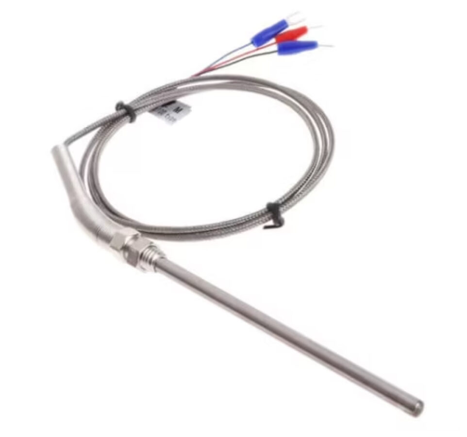
Resistance Temperature Detectors (RTDs - Pt100/Pt1000)

Known for exceptional accuracy (Class A RTDs offer ±0.15 °C accuracy at 0 °C) and stability over a moderate range (-200 °C to 600 °C). Although pricier and slower in response than TCs, RTDs offer excellent precision and consistent readings, ideal for industrial environments. Ideal for: Medium-range, precise industrial measurements such as environmental chambers, pipelines, reactors, or climate control systems.
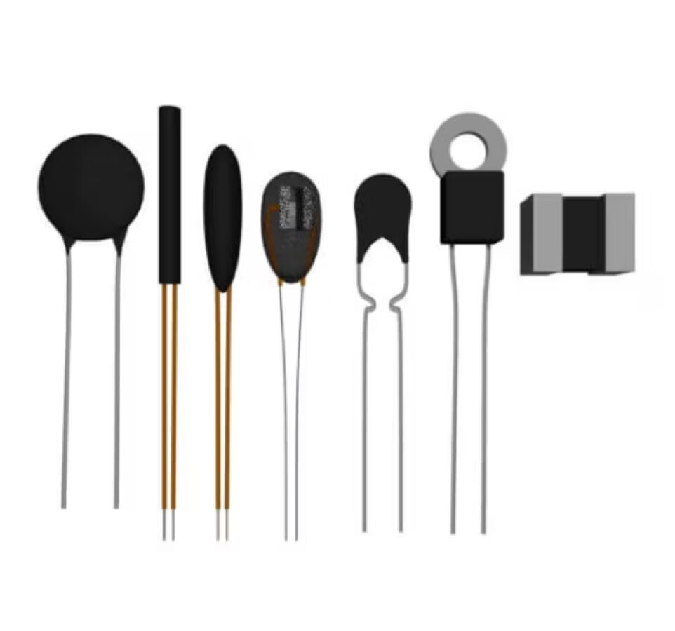
Thermistors (NTC)

Thermistors (NTC)

Highly sensitive within narrow temperature ranges (typically -40 °C to 150 °C), offering high resolution up to ±0.1 °C. Economical and responsive, but being non-linear, require calibration or software linearization. Ideal for: Narrow-range, high-resolution applications like electronics temperature monitoring, battery packs, or medical devices.

fiber optics scaled

Fiber Optic Temperature Sensors

Essential for environments with high electromagnetic interference (EMI) or high-voltage conditions. These sensors offer electrical isolation and immunity to electromagnetic interference (EMI), making them suitable for specialized high-voltage or EMI-sensitive applications. Ideal for: Transformer and motor winding temperatures, MRI machines, and high-RF environments. (initial release: contact sales for integrated solutions)


What’s the Bottom Line?

  • Thermocouples: Extreme temperature ranges, high durability, cost-effective for large quantities.
  • RTDs: Industrial settings requiring moderate temperatures and high precision.
  • Thermistors: Precise, localized measurements within narrow temperature ranges.
  • Fiber Optics: Specialized, high-voltage, or EMI-sensitive environments (integrated solutions—contact sales).
Use our product finder to select the right measurement modules for your sensor type, or contact our experts for personalized guidance on selecting the appropriate temperature probe.

Achieving Accurate and Stable Readings

Obtaining precise temperature measurements with industrial temperature sensors requires addressing several common challenges:

Calibration and Tolerance

Solution: Standard Type K TCs (±2 °C) or Class B Pt100 RTDs (±0.3 °C at 0 °C) have defined tolerances. Select higher-grade sensors (Class A, 1/10 DIN) or calibrate sensor-instrument systems at known points to enhance accuracy.

Stability and Drift

Industrial temperature sensors drift due to contamination, mechanical stress, or aging. TCs exposed to high temperatures degrade, causing readings to shift over time.

Solution: Regular calibration of temperature sensors and operating them within recommended conditions can help reduce drift.

Repeatability and Noise

Fluctuations caused by electrical interference or poor sensor coupling result in unstable readings.

Solution: Ensure proper temperature probe installation, good thermal contact (e.g., using thermal paste or adequate immersion), and utilize instruments with digital filtering (e.g., Gantner DAQ modules’ 50/60 Hz rejection filters) to stabilize measurements.

Cold Junction Compensation (CJC)

Incorrectly handled cold junction compensation can cause significant errors (>10 °C).

Solution: Always use instrumentation with built-in, precise CJC (e.g., Gantner Instruments’ thermocouple modules).

Instrumentation Accuracy

Measurement devices themselves contribute to overall uncertainty. Even high-grade sensors perform poorly on low-quality loggers.

Solution: Confirm your instrument’s specifications match your accuracy requirements. High-precision instruments like Gantner’s Q.series modules minimize this error (resolution down to 0.01 °C, accuracy typically ±0.1 °C or better).

Effectively managing these factors — sensor choice, calibration, proper installation, and quality instrumentation — is crucial to ensuring accurate and stable temperature measurements.

Managing Thermocouple Reference Junctions

Thermocouples measure temperature differences, not absolute values, requiring accurate cold junction compensation (CJC). Ignoring proper CJC can cause large errors (tens of degrees).

Understanding the issue

A thermocouple measures temperature difference, not absolute temperature. The meter or module needs to know the reference junction temperature (usually the terminal temperature) to compute the actual temperature at the sensing end. If you neglect this, errors the size of the ambient variation will creep in (which could be tens of degrees).

Solutions

  • Built-in Cold Junction Compensation: Built-in Cold Junction Compensation: Use DAQ modules with integrated temperature sensors (RTDs or thermistors) at terminal points. These automatically correct thermocouple voltage readings for variations in ambient temperature. Ensure your hardware is correctly set for your thermocouple type and verify internal CJC accuracy. Gantner modules include dedicated, highly accurate CJC circuitry.
  • External Reference: External references, such as ice baths or stabilized chambers (maintained at 0°C), are highly accurate, but add complexity. They are typically employed in calibration laboratories. Built-in Cold Junction Compensation typically suffices.
  • Terminal Stability: Ensure uniform temperature at terminal blocks to prevent variations or gradients (caused by drafts or hot electronics) that can lead to errors. Maintain stable ambient conditions or enclosures around terminals.
  • Correct Connectors and Wires: Always use thermocouple-grade connectors and extension wires to prevent unintended junctions that could affect accuracy. Dissimilar metals create unintended junctions, which can affect accuracy. Industry-standard TC connectors (color-coded by type) prevent such issues.

Key takeaway

Properly managing cold junction compensation is essential for accurate thermocouple measurements. Built-in CJC (as provided by Gantner’s DAQ modules) simplifies setup and ensures reliability—when correctly configured, thermocouple readings remain stable and accurate.

Special Tip: External Cold Junction Compensation Board (CJC30)

For installations involving large channel counts or long thermocouple cables, Gantner Instruments offers the external CJC30 board, supporting up to 30 TC channels.

Equipped with an integrated Pt1000 sensor for precise measurement of the cold junction temperature, the CJC30 board serves as an isothermal reference junction, significantly reducing cable complexity.

RTDs Wiring Configurations – 2-Wire, 3-Wire, 4-Wire

When connecting RTD temperature sensors or thermistors, you’ll encounter options for 2, 3, or 4-wire connections. This is a common area of confusion, but it’s all about dealing with lead wire resistance:

2-Wire: The simplest method uses just two wires, but the measurement includes sensor and lead resistance, which can introduce significant errors—e.g., 10 m of thin wire (~1 Ω) adds approximately 2.6 °C error for a Pt100. Suitable only for short distances or lower accuracy requirements; thicker gauge wires reduce this error.

3-Wire: Most common in industrial applications, a third wire compensates for lead resistance by measuring and subtracting it, assuming equal lead lengths and gauge. This greatly reduces error—from about 2.6 °C to typically less than 0.2 °C—making it the standard compromise between complexity and accuracy.

4-Wire (Kelvin): Provides the highest accuracy by using separate pairs for current supply and voltage sensing, entirely eliminating lead resistance effects. Recommended for precision measurements, calibration, or very long cable runs. The downside is complexity and additional wiring cost. Match sensors and instrumentation for maximum benefit.

Thermocouples are inherently two-wire and don’t face these configuration choices because lead resistance has minimal impact due to high input impedance; the main concerns are noise and junction integrity.

Best practice:

Always opt for a 3-wire setup for RTDs to significantly improve measurement accuracy. Ensure correct wiring per your DAQ module’s manual, and use properly color-coded cables to maintain balanced resistances.

Did you know?

If you need modules that allow comprehensive temperature measurements using RTD, NTC, and TC sensors alongside other measurement parameters, such as voltage, strain, and vibration, then choose Gantner Instruments, which provides high-performance multifunction I/O modules for enhanced test flexibility and data integration.

A107: 4 Analog Input Channels

•   Voltage: ±10 V, ±1 V, ±100 mV

•   Current: Up to ±25 mA

•   Resistance: 400 Ω to 4 kΩ

•   RTDs: Pt100, Pt1000

•   Strain Gages: ±2.5 mV/V, ±50 mV/V, ±500 mV/V

•   Potentiometers: 1 kΩ to 10 kΩ

•   Sampling Rate: Up to 20 kS/s per channel

A101: 2 Analog Input Channels

•   Voltage: ±100 mV to ±10 V, 0–60 V 
•   Current: 4–20 mA loops
•   Resistance: Up to 10 kΩ
•   RTDs: Pt100, Pt1000
•   Thermocouples: Types B, E, J, K, L, N, R, S, T, U
•   Strain Gages: Full, half, and quarter-bridge configurations
•   IEPE/ICP Sensors: For vibration and acoustic measurements
•   Sampling Rate: Up to 100 kS/s per channel

Dealing with Electrical Noise and Interference

“My temperature readings fluctuate whenever the motor runs!”—a common frustration when measuring low-level signals such as thermocouples. Here’s how to ensure accurate, stable readings by minimizing electrical noise and interference:

  • Use Shielded, Twisted-Pair Cables: Twisted pairs greatly reduce electromagnetic interference (EMI) by canceling magnetic field effects. Shielding further blocks external noise. Always ground the shield at one end only to avoid ground loops. TC and RTD sensor cables typically come pre-twisted; ensure this is standard practice.
  • Separate Sensor and Power Cables: Keep low-level sensor wires physically separated from power lines, motor leads, and PWM cables to prevent interference. If crossing is unavoidable, do so at right angles. Consider metal conduit or cable trays as physical shields.
  • Enable DAQ Filtering: Activate built-in filters on your measurement hardware. Low-pass or notch filters effectively reduce jitter and eliminate mains-frequency interference (50/60 Hz). Gantner modules offer selectable digital filtering to remove typical electrical noise, providing stable, clear readings. For slowly varying processes, software averaging can further smooth measurements.
  • Check Your Grounding Strategy: Ground loops cause subtle yet significant errors. Use isolated, differential inputs (like those provided by Gantner DAQ modules) to prevent ground currents from interfering with your signals. If grounding issues persist, consider using ungrounded thermocouples or carefully grounding only one end of your system at the DAQ side.
  • Proper Thermocouple Practices: Thermocouple signals are extremely small (in the microvolt range), making clean, secure connections vital. Loose or dirty connections can convert RF noise into measurable offsets. Many DAQ modules include built-in RC filters; if using general-purpose DAQ devices, consider adding small external RC filters (e.g., a 0.1 µF capacitor across inputs) to suppress high-frequency spikes.
  • Identify and Mitigate Specific EMI Sources: Common interference sources include variable-frequency drives, welding equipment, and radio transmitters. Identify these sources by testing sensor performance with equipment both on and off. If EMI persists, additional shielding, re-routing, or filters may be required.
  • Consider a Distributed DAQ Architecture: If noise persists despite these measures, consider shortening sensor cable runs by digitizing signals close to their source. Gantner’s distributed DAQ modules allow direct digitization at the sensor, significantly reducing noise susceptibility and ensuring robust signal transmission via fieldbus systems.
  • Diagnose Using Frequency Analysis: If problems persist, perform an FFT analysis to identify specific interference frequencies. Many Gantner systems integrate seamlessly with analytical software, enabling precise identification and targeted filtering adjustments.

Following these best practices ensures reliable, stable temperature measurements—free from the interference that often compromises accuracy.

Measuring Temperature on High-Voltage Systems Safely​

Accurately measuring temperature with industrial temperature sensors in high-voltage environments requires:

Use Isolated Measurement Modules

Select DAQ modules with high galvanic isolation (up to 1500 VDC).

Ensure Proper Sensor Insulation and Routing

Use sensors specifically rated for your voltage.

Avoid Grounded Sensors on HV Points

Choose ungrounded sensors to prevent ground loops.

Verify High Common-Mode Range Capability

Ensure your DAQ system handles high-voltage measurements.

Prioritize Safety with Expert Solutions

Follow expert solutions and safety protocols.


Always follow proper safety protocols, including lock-out/tag-out procedures, when installing and operating sensors in high-voltage setups.

Why Gantner for Temperature Measurement?

With over 40 years of proven experience, Gantner Instruments provides accurate, stable, and reliable temperature measurement solutions trusted by leading organizations worldwide. Our versatile data acquisition (DAQ) hardware is specifically engineered for challenging temperature measurement scenarios, from precision thermocouple and RTD measurements to specialized solutions for high-voltage and cryogenic environments.

Gantner Instruments enables you to achieve precise temperature measurement results, overcome technical challenges, and exceed your testing and monitoring requirements:

High Precision TC measurements
The A104 features 8 inputs for all types of thermocouples, along with an external cold junction compensation terminal. 50/60 Hz main rejection filter and thermocouple burnout (wire break) detection are standard features. Automatic linearization correction with optimal position of the interpolation points adjusted to measurement ranges ensures best-in-class accuracy up to +/-0.8 K

Standard miniature TC connectors
Whether you have a Type K, T, J, C, or any other standard thermocouple with a miniature connector, such as the A104 TCK, TCT, etc., this is the right choice. It comes with all the features of the A104 but makes the connection of thermocouples much easier. A TCx version is also available for all types of thermocouples, providing full flexibility.

Thin TC Wires or Noisy Environments
The A104+ should be used for high-resistive thermocouples with very thin wires. The burnout and wire break detection is optimized to minimize the influence on accuracy.
The high CMRR, achieved through specially separated input stages with anti-aliasing filters for each channel, makes the A104+ the perfect fit for measurements on power electronics, such as inverters, or in noisy environments.

RTD (Pt100/Pt1000) measurements
The A105 is a versatile module with 4 channels for Pt100 and Pt1000 (RTD) sensors. It supports 2-3-4 wire connections, providing the highest precision with a maximum of measurement errors of 0.05K and the lowest temperature drift.

Cryogenic temperature sensors
The CR Version of the A105 is used for cryogenic temperature sensors with resistances of up to 20 kOhm. The ultra-low excitation current minimizes the sensor self-heating and ensures measurements with the highest possible accuracy in ultra-low temperatures. Sensor-specific linearization, achieved by using 32 nodes and archives in a sensor data file, or the Import of manufacturers’ calibration data, makes the setup as easy as possible.

NTC sensors
The A105 10k is the variant for all types of NTCs. The measurement range of up to 100 kOhm, compared with 0.01 Ohm resolution, makes measurements down to -50 °C possible.

High-Voltage Thermocouple measurements
For thermocouples operating at high-voltage potentials, such as those found in batteries, fuel cells, electric motors, or inverters, the A124 provides 4-channel galvanic isolation up to 1200 VDC. It comes with different types of connectors for all thermocouple types. The A124 plus Version provides an isolation of 1500 VDC and enables measurements with Type K thermocouples, as well as on the latest battery packs.

RTD or NTC on high-voltage
Measurements with Pt100/Pt1000 (RTD) or NTC sensors are possible on up to 1200 VDC potential with the A121. This module provides two channels with 100 kS/s each.

Gantner Instruments enables you to achieve precise temperature measurement results, overcome technical challenges, and exceed your testing and monitoring requirements:

  • A104: High-precision thermocouple measurement
  • A104 TCK – Standard miniature thermocouple measurement connectors optimized for Type K temperature probes.
  • A104+ – Enhanced EMC-protected thermocouple measurement For thin TC wires or noisy environments
  • A105: Versatile RTD (Pt100/Pt1000) and NTC measurement module
  • A105 CR: Specialized low-current module for cryogenic measurements
  • A105 10k: Dedicated NTC measurement module for extended resistance ranges
  • A124: Thermocouple measurement module for high-voltage environments
  • A121: High-voltage RTD and NTC measurement module

Typical Applications Include:
Mobility (electric vehicle battery testing), aerospace (engine and structural tests), energy systems (fuel cells, renewables), and civil engineering (infrastructure monitoring).

Discover how Gantner Instruments can tailor a robust and flexible temperature measurement solution to meet your specific needs.

What our clients say

Application Examples

Gantner’s cutting-edge DAQ technology is trusted globally for applications in the mobility, aerospace, civil engineering, and energy sectors. Choose from the following industry examples to discover the most versatile DAQ on the market.

GM Hummer EV - Test and Measurement HW for A&D (GM Battery Lab Project)
New call-to-action

AE
Measuring temperature in components of Hybrid Electric Drives

For our client, a well-known German engineering and technology market leader, we delivered the testing application solution for temperature measurements of components and new materials of hybrid electrical drives.

Click here to request
access to every
GI Application Example

FAQ

These are frequently asked questions regarding our Temperature Measurement solution:

A thermocouple produces a small voltage proportional to the temperature difference between its measurement (“hot”) junction and reference (“cold”) junction (this is the Seebeck effect). Calculating or converting this voltage involves a few steps:

  1. Determine the type of thermocouple and obtain reference data: Each thermocouple type (K, J, T, E, etc.) has a well-characterized voltage-vs-temperature response (often provided by NIST tables or polynomial equations). You’ll need the data or formula for your thermocouple type to relate voltage to temperature.
  2. Measure the cold junction (reference) temperature: Unless your reference junction is exactly 0 °C (ice point), you must compensate for the fact that the reference end is not at 0 °C. Modern instruments have a built-in cold junction sensor to measure the terminal temperature.
  3. Find the reference junction equivalent voltage: Using the thermocouple’s table, find what voltage would be generated by that type of thermocouple at the reference junction temperature. For example, if using a Type K and your reference is 25 °C, the table might say this corresponds to about 1.00 mV. This is often called V<sub>ref</sub>.
  4. Measure the thermocouple’s output voltage (relative to reference): Let’s call this V<sub>D</sub>. This is the raw reading from the thermocouple wires.
  5. Add the voltages (cold-junction compensation): The effective thermocouple voltage as if the reference were 0 °C is V<sub>t</sub> = V<sub>D</sub> + V<sub>ref</sub>. In other words, we mentally “move” the reference to 0 °C by adding the reference junction’s equivalent voltage.
  6. Convert total voltage to temperature: Now using the Type’s standard curve, find the temperature that corresponds to the voltage V<sub>t</sub>. That will be the measured temperature at the hot junction.

For example, suppose you have a Type K thermocouple: the reference junction is at 22 °C (which, for Type K, is ~0.87 mV from the table) and the measured voltage from the thermocouple is 3.41 mV. Adding them gives V<sub>t</sub> = 3.41 + 0.87 = 4.28 mV. Looking up 4.28 mV in the Type K table (or using the polynomial), you find that it corresponds to about 100 °C. This would mean the hot junction is ~100 °C. Many DAQ devices do all this internally: the cold junction sensor reading is used to automatically apply the compensation and convert the thermocouple voltage to a temperature reading. If doing it manually, use official thermocouple tables for accuracy, especially for higher temperatures where the voltage-temperature relationship is non-linear.

Thermocouple types (J, K, T, E, N, etc.) can be identified in a few ways, most commonly by the color coding of their wires or connectors, and by the magnetic/physical properties of the wires:
ANSI color code (North America): In ANSI/ASTM standards, red is the negative lead for all thermocouple types. The positive lead has a distinctive color for each type:

  • Type K: Positive wire is yellow, negative wire is red. (Type K = Chromel/Alumel; the Alumel negative is magnetic.)
  • Type J: Positive wire is white, negative wire red. (J = Iron/Constantan; the iron positive is magnetic.)
  • Type T: Positive wire is blue, negative wire red.
  • Type E: Positive wire is purple (sometimes violet), negative wire red.
  • Type N: Positive wire is orange, negative wire red.
  • (Type S/R: often black or green overall, with wire colors varying by manufacturer; Type B: usually gray overall in ANSI).

For example, a thermocouple with one yellow and one red lead is Type K, whereas one with blue and red leads is Type T.
IEC color code (Europe): Uses different colors (e.g., Type K positive is green in IEC, Type T positive is brown, etc., and negative is white in many cases). So be aware of the standard in use; often the overall cable jacket has a color too (IEC Type K jacket is green, Type J is black, Type T is brown, etc.).
Check markings: Some thermocouple connectors or cables have the type letter embossed or printed on them. For example, miniature thermocouple connectors are often color-coded (yellow connector for Type K, etc.) and may have the letter on the plastic.
Material/magnetic test: Type J has a magnetic iron wire; Type K’s Nickel-Chromium/Nickel-Alumel are partially magnetic (the Alumel is magnetic, Chromel is not). Type T’s copper wire is obviously copper-colored and non-magnetic, etc. This can sometimes help distinguish (e.g., if one wire is magnetic and one isn’t, that could indicate Type K). However, using color codes is simpler and more reliable.
Suppose the thermocouple wires have lost their insulation or have no obvious color. In that case, you might perform a calibration test: connect the pair to a thermometer reader and see the voltage generated at known temperatures, then compare with standard tables. The voltage response (Seebeck coefficient) differs by type (e.g., Type K ~41 µV/°C around room temp, Type T ~42 µV/°C, Type J ~52 µV/°C at 0–100 °C). This requires sensitive equipment, but it can identify the type by the voltage curve.
In summary, the easiest way is by insulation color coding per standards – for instance, a yellow/red thermocouple is Type K, white/red is Type J, blue/red is Type T, purple/red is Type E, orange/red is Type N in the ANSI system. Always ensure you know which standard is being used, and when replacing or extending thermocouples, match the type exactly (you must use thermocouple-grade extension wire of the same type for accuracy).

Explore Our Temperature Measurement Products

Our online Product Finder can guide you to the appropriate modules based on sensor type and performance needs. Browse our comprehensive temperature measurement modules, optimized for diverse and demanding applications:

DAQ SERIES

DAQ Interface

Form Factor