Strain
Measurement
Strain measurement is a critical process used in assessing the behavior of materials under stress, providing vital data for evaluating structural integrity and performance. This fundamental physical property quantifies the deformation of materials relative to their original dimensions, allowing engineers and scientists to understand how materials will react under various conditions. Invented in 1938 by Edward E. Simmons and Arthur C. Ruge, strain gauges, also called strain gages, are pivotal tools for capturing this data. Strain gauge sensors show changes in resistance when stretched or compressed. They reveal the minute alterations within a material subjected to force. Their application ranges from simple laboratory experiments to the comprehensive monitoring of large-scale structures such as bridges and skyscrapers. This ensures safety and durability.
The Principle of Strain Measurement
At the heart of strain measurement is the strain gauge, a device based on the principle that the electrical resistance of a material changes in response to mechanical deformation. A common type is the metallic foil strain gauge, which consists of a thin pattern of foil adhered to a backing material. This strain gauge is applied to the surface of a test specimen; as the specimen deforms, the foil deforms, changing its electrical resistance in a quantifiable way.
Alongside individual strain gauges, strain gauge rosettes are employed to comprehensively measure strain along different directions on a material’s surface. These rosettes consist of three or more strain gauges oriented at specific angles to each other, enabling the precise determination of the complete strain state at a single point. This capability is particularly valuable in complex stress analysis, where understanding the multidirectional strain is critical.
The gauge factor (GF) is a key parameter in strain gauge technology, indicating the strain gauge’s sensitivity to strain by quantifying the relationship between strain and resistance change. This calculation is crucial for utilizing strain gauge amplifiers effectively in a Wheatstone bridge setup, which amplifies the measurement’s sensitivity and accuracy. Engineers can select from three different configurations: quarter bridge strain gauge, half bridge strain gauge, or full bridge strain gauge configurations. Each configuration offers unique advantages in terms of sensitivity and temperature compensation, making them suitable for a variety of strain measurements.
- Quarter Bridge Configuration: Incorporates a single active strain gauge, typically used for simple, uniaxial strain measurements or where minimal strain is expected.
- Half Bridge Configuration: Utilizes two strain gauges in opposing arms of the bridge, doubling the sensitivity and partially compensating for temperature-induced errors.
- Full Bridge Configuration: Employs four strain gauges, maximizing sensitivity and offering full compensation for temperature effects, ideal for precise, bidirectional strain measurements.
Where is Strain Measurement used?
Civil Engineering and Geotechnical Monitoring
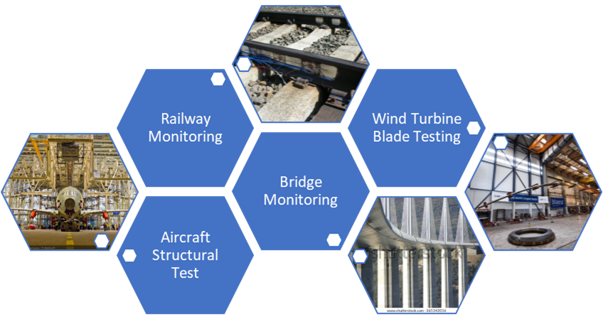
Strain gauges aid in the structural health monitoring of buildings, bridges, dams, and other key infrastructures. Given the catastrophic consequences of structural failures, these gauges are deployed for continuous monitoring, capturing data that can predict and prevent incidents leading to injuries or fatalities. The precision of strain gauges, coupled with their robustness and low maintenance requirements, allows for long-term deployments even in remote or difficult-to-access areas.
Aerospace Applications
Strain gauges are extensively used in structural testing to validate the integrity of airframes and components. Engineers use simulation and measurement to test the effects of dynamic forces on aircraft structures. This verifies computational models and ensures compliance with safety standards. Turbulence and aerodynamic stress are examples of such forces. The application of strain gauges in aerospace testing entails both static and dynamic analyses. This dual approach, combining real-world testing with simulations (CAD and FEA), enhances the reliability of aerospace designs and contributes to the overall safety of air travel.
Automotive and Mobility
In the automotive sector, strain measurement technologies enable engineers to optimize structures for strength, durability, and efficiency, ensuring that vehicles can withstand the rigors of operation without unnecessary weight. Electric vehicle battery testing, in particular, benefits from strain gauge analyses to evaluate the mechanical stresses batteries endure during operation, contributing to safer, more reliable energy storage solutions.
Renewable Energy Systems
The renewable energy industry, especially wind power, relies on strain gauges to monitor the structural integrity of wind turbine components. These gauges help predict maintenance needs, extending the lifespan of turbines and preventing failures that could lead to power outages or safety hazards. By accurately measuring the strain on turbine blades and towers, engineers can optimize designs for durability and performance, even in the face of variable and extreme environmental forces.
Enhances strain gage measurements by overlaying a high-frequency signal, reducing noise for clearer, more accurate results.
Our modules are capable of measuring full bridge strain gauge, half bridge strain gauge, and quarter bridge strain gage, ensuring flexibility for any project requirement.
For advanced applications, our universal analog input DAQ modules offer extended capabilities, including various bridge measurements, programmable sensor excitation up to 12 V, and a ± 10 V or 0-20 mA analog output.
Challenges in Strain Measurement
Environmental and Electrical Noise Interference
One of the foremost challenges is the interference caused by environmental and electrical noise. Strain gauges, being highly sensitive devices, can pick up extraneous electrical signals from nearby machinery, power lines, or even atmospheric conditions. This noise can obscure the true strain signal, making it difficult to isolate and measure the desired data accurately. Engineers must employ sophisticated noise-reduction techniques, such as shielding, filtering, and the use of carrier frequency amplifiers, to mitigate these effects and ensure the integrity of strain data.
Thermal Drift and Compensation
Thermal drift represents another significant hurdle. Temperature changes can cause both the material under test and the strain gauge itself to expand or contract, introducing apparent strains that do not originate from mechanical stress. This phenomenon can lead to erroneous readings, particularly in environments with fluctuating temperatures. To address this issue, strain gauges are often paired with temperature compensation techniques, such as the use of dummy gauges or active temperature correction circuits, to subtract thermal effects from the measured strain.
Installation and Gauge Alignment
Accuracy is also heavily dependent on the correct installation and alignment of strain gauges. A misaligned gauge can produce skewed data, not accurately representing the strain within the material. Ensuring proper gauge placement, orientation, and adhesion is crucial, especially when measuring complex or irregularly shaped objects. This often requires meticulous preparation of the surface, precise application of the gauge, and rigorous testing to confirm that the installation reflects the true mechanical stresses at play.
Material and Surface Properties
The characteristics of the material being tested pose additional challenges. Different materials respond to stress and strain in diverse ways, influenced by factors like anisotropy, heterogeneity, and surface texture. These properties can affect how strain is distributed and measured, necessitating customized gauge selection and placement strategies. Additionally, surface preparation, including cleaning and smoothing, is vital to ensure that the gauge adheres well and provides accurate measurements.
Selection of Wheatstone Bridge Configuration
The choice of Wheatstone bridge configuration—quarter bridge, half bridge, or full bridge—adds another layer of complexity. Each configuration offers different advantages in terms of sensitivity, temperature compensation, and the ability to measure different types of strain (e.g., axial, bending, shear). Engineers must carefully select the appropriate bridge setup based on the specific requirements of their measurement task, balancing factors such as accuracy, sensitivity, and environmental compensation.
Calibration and Signal Processing
The calibration of strain gauge measurement systems and the processing of strain signals are critical to obtaining accurate results. Calibration ensures that the strain gauge and measurement system accurately translate strain into electrical signals, accounting for factors like gauge factor variability and system nonlinearities. Signal processing techniques are then used to extract meaningful data from these signals, requiring advanced algorithms to filter noise, compensate for drift, and analyze the strain patterns.
Technical Solutions to Measurement Challenges
By leveraging sophisticated data acquisition technology, we provide engineers with the tools needed for comprehensive strain gage measurement, enabling precise stress analysis and the enhancement of material performance and safety across industries.
Gantner Instruments offers a comprehensive solution to the challenges of strain measurement, incorporating advanced features such as:
- High-resolution Strain Amplification: Our strain gauge amplifiers are equipped with a 24-bit sigma-delta A/D converter. This significantly reduces quantization noise, providing a high signal-to-noise ratio (SNR) that is essential for capturing accurate strain measurements.
- Adjustable Measurement Range: Our modern measuring amplifiers feature adjustable measurement ranges with a gain accuracy of ± 0.05%. This precision allows for minimal full-scale error, critical in applications requiring detailed stress analysis and fatigue monitoring.
- Optimal Bridge Excitation Voltage: To counteract the thermal drift caused by strain gauge self-heating, our amplifiers utilize pulse bridge excitation. This method minimizes measurement errors, ensuring the data reflects actual material deformation.
- Automatic Lead Wire Resistance Compensation: Our DAQ systems automatically correct for changes in lead wire resistance, eliminating the need for manual shunt calibration and enhancing the reliability of strain measurements.
- Carrier Frequency Technology: This technology improves signal quality during measurement by eliminating frequencies and harmonics outside the carrier frequency bandwidth. This is crucial for environments with significant electrical noise.
Professional DMS Signal Measurement Modules

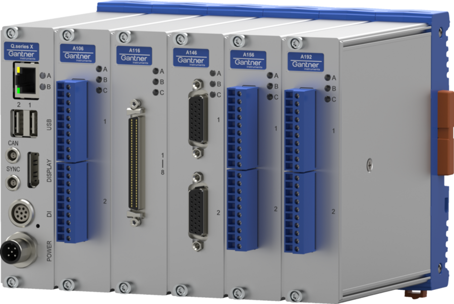
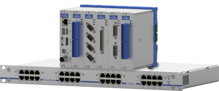
Our Q.series X modules are designed to overcome the various hurdles of strain measurement, to accommodate various strain gauge wheatstone bridge configurations, and provide the necessary strain gauge resistance optimization for comprehensive strain gage measurement,
- A101: A multifunctional module with a sampling rate of 100 kHz.
- A102: A fast module with analog output
- A106: A universal bridge module with selectable DC and TF-input for versatile strain gauge configurations.
- A107: A budget-friendly 4-channel module with a sampling rate of 10 kHz
- A116: Ideal for quarter-, half-, and full-bridge measurements, offering high stability with 120-Ω and 350-Ω padding resistors for exceptional temperature stability.
- A136: A versatile 4-channel module with selectable excitation up to 10 V and 20 kHz sampling, perfect for dynamic strain gauge measurement scenarios.
- A146: A 16-channel module for quarter bridges at 10 kHz / channel
Product Example: Measuring Module A106
Offers flexibility with DC Voltage Supply and Carrier Frequency Feed Supply options, catering to different strain gauge setups and minimizing the impact of cable capacitance and environmental noise.
DC Voltage Supply
Suitable for high-impedance measuring bridges and long cables between transducer and measuring device. With DC power, cable capacitance shows no effect.

Carrier Frequency Feed Supply
Only modulated signals are transmitted. Therefore, carrier frequency devices show better drift, noise, and susceptibility behavior.

TF 4.8 kHz
Suitable for DMS and inductive transducers. Nevertheless, longer cables may induce phase shifts between the supply and the measurement signal causing reduced sensitivity.
TF 600 Hz
This carrier frequency is suitable for high accuracy needs. Cable capacitance shows no considerable effect.
Product Example: Measuring Module A116
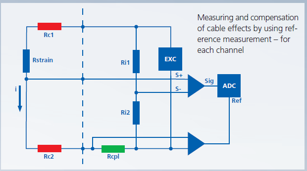
Ideal for compact and accurate strain measurements, supporting up to 8 channels for quarter-, half-, and full-bridge configurations, and ensuring stability with 120-Ω and 350-Ω padding resistors for high-temperature environments.
- Measuring and conditioning of up to 8 parallel channels with 10 kHz – no multiplexing
- Compensates cable interferences by simultaneous reference measurement of the voltage drop
- 120-Ω and 350-Ω padding resistors – 0.05 ppm / K – for high-temperature stability
- Shunt resistor for detecting changes during the measurement
- Measuring range 2,000 μm / m and 20,000 μm / m for easy adjustment to the signals
- Q.station allows synchronous detection (jitter 1 μs) of several hundred channels
The stability of the measurement with single-DMS is mainly dependent on the temperature sensitivity of the padding resistors:
A 350-Ω strip changes its resistance at 1000 μm / m (k=2) to 700 mΩ. The temperature stability of the A116 padding resistor is 0.05 ppm / K, which corresponds to 0.025 μm / m per degree of temperature change or 0.025% / 10 K. If resistor stability is only 5 ppm / K, for example, the deviation will be 2.5 μm / m per degree or 2.5% / 10 K.
Product Example: Measuring Module A136
The A136 stands as a highly versatile and precise measuring module in the Q.series, ideal for a range of strain gauge applications.

- Equipped to handle up to 4 parallel channels, the A136 offers a high sampling rate of 20 kHz per channel and 24-bit ADC strain amplification, capturing detailed data without multiplexing.
- It supports a variety of bridge-based sensors, with built-in completion resistors for 120, 350, and 1000 ohm versions, ensuring broad sensor compatibility.
- It comes with built-in completion resistors and is compatible with both 4- and 6-wire configurations.
- The module allows for selectable excitation levels up to 10 V, accommodating a wide range of measurement requirements.
- The A136 is designed for seamless integration with both Q.station and EtherCAT systems, ensuring versatility in system setups.
The A136’s ability to provide high-resolution measurements is especially valuable in dynamic environments where accuracy and rapid data collection are crucial. Its flexible configuration and compatibility with various sensor types make it an indispensable tool for engineers in advanced measurement scenarios.
Elevate Your Strain Measurement Practice
When using strain gages, variations in ambient temperature are the most common causes of measurement error. A temperature-related change in bridge resistance as small as 0.1% could result in an elongation of 500 µm/m. You want to avoid your strain measurement turning into a temperature measurement.
Download our free white paper to learn about the importance of selecting the correct bridge completion resistor. Additionally, you will discover effective techniques for reducing noise and compensating for errors in long sensor cables, giving you the knowledge to optimize your strain gage measurements.
Trusted by Industry Leaders
Our commitment to innovation and precision has earned the trust of industry leaders worldwide.


Application Examples
Gantner’s cutting-edge DAQ technology is trusted globally for applications in the mobility, aerospace, civil engineering, and energy sectors. Choose from the following industry examples to discover the most versatile DAQ on the market.
AE
Measuring temperature in components of Hybrid Electric Drives
Click here to request
access to every
GI Application Example
FAQ
These are frequently asked questions regarding our Strain Measurement challenge:
Strain is typically measured using a strain gauge sensor bonded to the object of interest. As the object deforms under load, the strain gauge stretches or compresses, causing a small change in its electrical resistance. By wiring the gauge into a Wheatstone bridge circuit and providing a stable excitation voltage, one can measure the minute voltage imbalance that corresponds to the strain. In practice, the bridge output (in millivolts) is amplified and converted to strain (ε) using the gauge’s known gauge factor. This method allows extremely small deformations to be quantified (e.g., 500 µε causes only ~0.1% change in a 120 Ω gauge). Other methods, like optical digital image correlation or fiber optic gauges, exist, but the bonded electrical strain gauge is the most common for directly measuring material strain.
To measure strain with a strain gauge, you must bond the gauge to the test object and connect it to a measurement device (usually via a Wheatstone bridge). In a quarter-bridge setup, the strain gauge forms one arm of the bridge, with fixed resistors in the other arms. When the object experiences strain, the gauge’s resistance changes, producing a small differential voltage in the bridge. A strain gauge amplifier or DAQ system then amplifies this output. The amplifier is configured with the gauge’s specifications (gauge factor, bridge type, excitation voltage, etc.), so it can convert the measured millivolt-per-volt signal into strain units. In summary, install the gauge properly, wire it into a bridge, provide excitation, and use instrumentation to read the voltage change, which is proportional to strain.
Reading a strain gauge’s output involves converting the raw electrical signal to mechanical strain. First, measure the gauge’s output voltage (often in mV) via the Wheatstone bridge under no-load (for zero offset) and under applied load. The bridge equation and gauge factor give the relationship between the voltage and strain. For practical calibration, a known strain can be applied (or a shunt calibration resistor used) to produce a reference voltage change. Modern DAQ software simplifies this: you input the gauge factor and bridge type, and the system scales the mV/V reading into strain (microstrain) automatically. For example, if a quarter-bridge with gauge factor 2.0 outputs 1 mV/V under load, the software will calculate the strain as ε ≈ 500 µε (since 1 mV/V corresponds to 0.0005 strain in this case). In essence, you measure the bridge output and apply the gauge’s calibration factor to get strain.
A strain gauge is a sensor that converts mechanical deformation into a change in electrical resistance. It typically consists of a thin metallic foil pattern arranged in a grid and bonded to a flexible backing. When glued to a structure, the strain gauge deforms along with the material. Stretching the gauge makes its conductors longer and thinner, increasing resistance; compression does the opposite. By measuring this resistance change (usually with a Wheatstone bridge and instrumentation), one can determine the strain in the material. Strain gauges were invented in 1938 and are widely used in experimental stress analysis and sensor construction because of their accuracy and simplicity.
Strain is a dimensionless quantity because it is defined as the ratio of change in length to original length (ΔL/L). Therefore, it has no units. In practice, strain is often expressed in terms of a small unit like microstrain (µε), which is 1×10^(-6) (i.e., one part per million) of strain. For example, a strain of 500 µε means a 0.000500 (0.05%) change in length. Sometimes you will see strain written as “in/in” or “mm/mm” to emphasize it’s a ratio, but these are technically unity. Using microstrain makes the numbers more convenient since typical structural strains are on the order of tens to thousands of µε.
- Choosing the right strain gauge involves several considerations about your application:
- Gauge pattern and geometry: Select a gauge configuration that matches the strain field. For instance, use linear gauges to measure uniaxial strain, or a rosette (with 2 or 3 gauges in known orientations) to measure strain in multiple directions.
- Gauge length: The length of the strain-sensitive grid should suit the size of the strain region. A shorter gauge (e.g., 3 mm) measures strain at a more local point, whereas a longer gauge (e.g., 10 mm) will average the strain over a larger area – useful if the strain field is not uniform.
- Resistance value: Common foil strain gauges come in 120 Ω or 350 Ω. A 120 Ω gauge draws more current (more self-heating) but is often more robust and cost-effective; a 350 Ω gauge gives a larger output signal and is better for use with long lead wires (less signal loss). For high-precision or battery-powered setups, higher resistance is preferred to minimize heating and power draw.
- Temperature compensation: Choose a gauge alloy and backing that match the thermal expansion of your specimen. Strain gauges are available with self-temperature-compensation codes (e.g., matched to steel, aluminum, etc.) so that thermal expansion of the specimen doesn’t create spurious strain readings. Ensure the gauge’s stated compensation (often indicated by a code like “Matching Coefficient 13 for steel”) suits your material.
- Environment and bonding: Consider operating temperature range and environmental conditions. Some gauges have special backing materials for high temperatures or are waterproofed for outdoor use. Likewise, select an appropriate adhesive and protective coating if needed.
- Connections and installation: Gauges come with different leadwire options (solder pads, pre-attached leads, etc.). If your application faces vibration or repeated loading, gauges with flexible leads or solder tabs that relieve strain on the wire connections are beneficial.
In summary, match the gauge’s pattern, length, resistance, and material properties to the mechanics and environment of your test. For example, a 350 Ω linear gauge of moderate length with self-compensation for steel, and a 3-wire lead, might be chosen for measuring bending strain on a steel beam. Always consult the manufacturer’s selection guide – key criteria typically include geometry, grid material, backing, length, resistance, and temperature response.
“Carrier frequency” generally refers to a high-frequency signal that is used as a carrier for transmitting information or for excitation in measurement systems. In communications, for example, a radio station has a carrier frequency (say 100 MHz) which is modulated with audio signals. In the context of sensors and instrumentation, carrier frequency excitation is often used with bridge sensors (like strain gauges or load cells) to improve measurement stability. Instead of a DC excitation, an AC excitation at a fixed carrier frequency (e.g., a few kHz) is applied to the sensor bridge. The sensor’s resistance change then modulates this carrier signal (similar to AM modulation). The measurement device demodulates the returned signal to determine the resistance change corresponding to strain or force. This AC carrier technique offers advantages: it can minimize the effect of thermal EMFs and 1/f noise, and it allows using narrow-band filtering to reject noise at other frequencies.
For example, a carrier-frequency amplifier might drive a strain gauge bridge with a 5 kHz sine wave. When the strain gauge is stressed, it modulates that 5 kHz signal slightly. The amplifier only listens at 5 kHz (and not at DC), so it ignores drift and low-frequency noise, greatly improving stability and noise rejection. The output is then demodulated back to a DC value proportional to strain. In summary, the carrier frequency is the frequency of the excitation or carrier wave being used. In a measurement system context, it’s a known, fixed frequency at which the system operates to encode the measurement signal. For communications, the radio wave frequency carries the information. In both cases, it’s the central frequency of a system that is being modulated with the desired information.
