Strain gages have endless uses in structural test and monitoring applications. Are you getting the most signal out of your strain amplifier? In this blog, we share eight tips to help you choose the right strain gage amplifier for your data acquisition system.
For which applications can strain gage measurements be used?
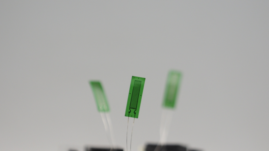
Strain gage technology has practically unlimited uses in structural test and monitoring applications, like durability testing of structural components in the automotive and rolling stock industry. The use of strain gage technology in aviation, military, and space applications has a long history. Strain gages are bonded directly to structural load-bearing components for static and fatigue testing of components and sub-assemblies. In the renewable wind energy industry, strain gage technology is applied to test the structural performance of wind turbine blades and bearings and structural health monitoring of wind turbines in the field. Strain gages may also be used to monitor civil engineering structures (bridges, tunnels, railways, dams), oil and gas pipelines, or nuclear plants.

Why is choosing the right strain amplifier so important?
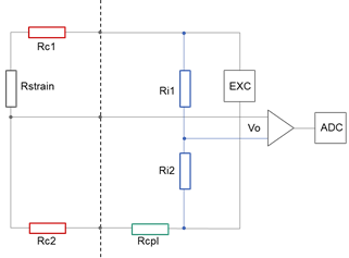
The most common way of strain measurement is using a single strain gage in a three-wire quarter-bridge configuration. This quarter-bridge configuration brings specific challenges for proper signal conditioning. The importance of taking care in selecting a strain amplifier cannot be understated – a wrong choice could cost more in time and money in the future.
Here are eight tips to help make the right choice for a strain gage amplifier for your data acquisition system.
1. Getting the most signal out of your strain amplifier
A quarter-bridge circuit is a single-ended input measurement, which means that the voltage between the input signal and the analog ground is measured. This difference is then amplified before it is fed through the analog-to-digital converter (ADC). Single-ended inputs can suffer from noise as the wire that carries the signal picks up any electrical background noise. The signal on a single-ended input could also be subject to ground loops. Best practices include using a foil-shielded, twisted pair cable for the wiring to the strain gage. Connect the cable shield on one end to the chassis ground of the signal conditioner. Consider increasing the amplitude of the excitation voltage. However, tradeoffs are associated with increasing the excitation voltage amplitude, which will be discussed later in this blog. Finally, select a strain amplifier with a 24-bit sigma-delta A/D converter—a higher resolution results in lower quantization noise and thus in a higher signal-to-noise ratio (SNR). In addition, sigma-delta ADCs use oversampling, filtering, and noise shaping to achieve highest resolution. One can accurately amplify even small-signal voltage levels.
2. Measurement range matters
Measuring amplifiers provide both accuracy and stability to the signal conditioning process. Strain gages need measuring amplifiers to boost the low-level measurement signals from the Wheatstone bridge before feeding them to the ADCs. One should adjust the amplifier gain to provide the full-scale output of the strain gage over the ADC’s entire range. Accuracy is influenced by the measurement range and amplifier’s gain accuracy. More modern measuring amplifiers provide adjustable measurement ranges with a gain accuracy of ± 0.05 %. A measurement range of ± 2000 µm/m would result in a full-scale error of only 1 µm/m. And a wide measurement range of ± 20,000 µm/m for crack detection would have a full-scale error of just 10 µm/m. Therefore, gain accuracy in combination with an adjustable measurement range is one of those specifications to look out for when selecting a strain amplifier.
3. Measure strain, not temperature
The strain obtained from a measurement at room temperature is considered accurate if performed at unchanged environmental conditions. But when the temperature changes, the specimen material expands, which will result in an unwanted strain reading. The temperature change also affects the metal grid and the strain gage’s thermal coefficient, a process called thermal output or temperature-induced apparent strain. Selecting a self-temperature compensated (STC) strain gage that is designed to adjust the thermal coefficient of the gage to match the expansion coefficient of the specimen’s material largely, but not entirely, compensates for the thermal output. Residual apparent strain in the form of a strain offset remains. If the gage temperature and the apparent strain characteristics are known, this offset can be calculated, and the strain value compensated accordingly. Two common techniques to correct or compensate for errors due to thermal output are (a) using an unstrained dummy gage for compensation or (b) applying a computational correction based on the measured gage temperature.
4. Choosing the optimal bridge excitation voltage
Thermal drift due to strain gage self-heating causes an apparent change in the strain that is not actually due to the deformation of the specimen. The higher the excitation voltage supplied to the gage, the more power, the more heat generated by the current running through the wires. For specimens with poor heat conductance, like composite materials, or when very small strain gages are used, lowering the excitation voltage or using a strain gage with higher resistance is a point of paramount significance. When selecting an appropriate bridge excitation voltage level, two opposing considerations exist: 1) a higher bridge excitation voltage improves the signal-to-noise ratio of the gage, 2) a lower bridge excitation voltage reduces thermally induced errors in strain gage measurement. The excitation voltage must be coordinated with the gage and the material to which it is bonded. Most strain gage manufacturers provide data curves representing general recommendations or starting points for determining optimum excitation levels. When measuring strain in a low-temperature or cryogenic environment, minimizing excessive energy to avoid sensor heat dissipation is even more crucial. Just reducing the excitation to an absolute minimum is not a solution because of a lower signal-to-noise ratio. In this case, a strain amplifier that provides a pulse bridge excitation will help to minimize the error due to sensor self-heating.
5. Pay attention to the stability of the completion resistor
Whether it is a fatigue test or a structural health monitoring application, a strain measurement campaign can run for several weeks up to several months. Often during day and night. Variations in ambient temperature are amongst the most common causes of measurement error when using a quarter-bridge circuit. Because the active strain gage and the passive bridge completion resistor are switched in series, resistor drift directly affects the measurement accuracy. A temperature-related resistance change as small as 0.1 % could result in an elongation of 500 µm/m. The Temperature Coefficient of Resistance, or TCR, is one of the leading used parameters to characterize the stability of a bridge completion resistor. The TCR defines the change in resistance as a function of the ambient temperature. The typical way to express the TCR is ppm/K, which stands for parts per million per 1-kelvin change in temperature. All too often, resistors with a high TCR are used to save on cost, resulting in unwanted errors or forcing you to program complex temperature correction curves. You want to avoid that your strain measurement turns into a temperature measurement!
6. Avoid measurement errors with long cable runs
Long cable runs are sometimes unavoidable. The resistance of lead wires that connect a strain gage into a Wheatstone bridge attenuates the bridge output or ‘desensitizes’ the gage. As the attenuation is a function of the length of the bridge wires, it will have a more significant effect with increasing cable length. With traditional strain amplifiers, a manual shunt calibration process must be performed before starting the measurement. The shunt calibration process determines the lead wire resistance and subsequent correction factor. Although widely applied, this method does not compensate for changes in lead wire resistance during the actual measurement, for example, due to ambient temperature fluctuations. A proven method for continuous correction of lead wire resistance is through ratiometric sensing of the internal bridge completion resistor that automatically corrects for measurement errors due to lead wire resistance, even during the measurement itself. There is no need for manual shunt calibration, thus also eliminating operator errors.
7. Knock out noise with carrier frequency technology
Does your setup have noise interference nearby, maybe even an electric or AC motor? These are significant sources of electric noise when measuring low voltage signals like strain gages or strain-based sensors. Strain gage measurements are plagued with noise and an offset drift that increases as the duration of your measurement increases. Carrier frequency amplifiers provide many benefits in these scenarios. The advantage they give versus direct voltage amplifiers is eliminating all frequencies and following harmonics outside of the carrier frequency bandwidth. This eliminates thermoelectric voltage noise, power line frequencies, and the resonance frequencies of motors nearby. These are all the primary noise signals that measurement engineers filter out of their data sets during initial post-processing before analysis. Having it eliminated when the data is collected in real-time improves the quality of viewing signals during the measurement and improves the signal integrity if used for a control signal.
8. Go for optical strain gages in extreme environments
An optical strain gage, or fiber optic strain sensor, based on fiber Bragg grating (FBG) offers an alternative method to collect high-quality strain measurements within harsh environments unsuitable for resistive strain gages. It detects changes in light transmission when the object attached to it experiences a load. An optical strain gage’s key feature is that they do not need electricity or an excitation voltage to operate, making them suitable for use in environments that will experience high levels of electromagnetic interference. Optical strain gages are inherently galvanically isolated, ideal for high-voltage location strain measurements. Optical strain gages provide long-term signal stability and system durability. Even at high-level vibration loads, they are far less subject to mechanical failure. Because optical sensors experience only minimal signal attenuation, the integrity of the data remains high, even if the data acquisition system is located several kilometers away, making optical sensors a popular choice for civil and railway infrastructure monitoring. To measure the signal coming from an optical strain sensor, you need an optical interrogator that measures the wavelength associated with the light reflected by the optical sensor and then converts it into understandable engineering units.
How to avoid that your strain measurement turns into a temperature measurement?
Download our free white paper to understand the importance of choosing the right bridge completion resistor. In addition, you will learn how to reduce noise with our carrier frequency technology and automatically compensate for measurement errors caused by long sensor cables.

More articles
Webinar on Electric Vehicle Testing and Key Trends & Developments in the EV Test Equipment Industry
Webinar: Trends, developments, and upcoming opportunities in the EV Testing, Validation & Certification Industry.
Read more...Q.series X D101 SV: Digital Measurement Module with Sensor Supply
The Q.series X D101 4 x Lemo 2B SV from Gantner Instruments is a digital measurement module that has been engineered to facilitate a broad spectrum of digital signal processing tasks. It is designed with a focus on providing accurate and rapid data acquisition for industrial applications that require high-performance measurement capabilities with integrated sensor excitation.
Read more...Enhanced Functionality with GI.bench’s Newest Release: Revamped UI, Powerful Tools and More!
Introducing the latest update to our powerful and intuitive testing and measurement software - GI.bench. This update promises to elevate your testing capabilities with features designed to streamline your workflow and maximize productivity.
Read more...Gantner Instruments Environment Solutions celebrates its 10th company anniversary and starts with a ground-breaking ceremony for the construction of another company building
Over the past ten years, Gantner Instruments Environment Solutions GmbH has grown into a global market leader of monitoring and control solutions for large-scale solar systems.
Read more...